Coil Design. The use of intermediate frequency (IF) coils and interstage coupling transformers were a major feature of vacuum tube based receivers. Both served the dual purpose of impedance matching and frequency selectivity.
What is a IF transformer?
What are IF amplifier filters? IF amplifier transformers are simply tunable inductors, usually with an integral fixed capacitor, and are typically used inside cheaper transistor radios. Mostly they are used as “synchronously tuned filters” because each stage is coupled by an active device.
How to test an IF transformer?
Separate the transformer from the input circuit. Test the input with your DMM. If the input power climbs to the expected value, the primary of the transformer is bad. If the input power does not climb to the expected value, then the problem lies not with the transformer, but with the input circuitry.
What is RF transformer?
An RF transformer is an electromagnetic device that sits between two or more circuits and uses changes of electric signals and the principle of induction in a conductor to produce a varying magnetic field (flux) that couples energy through to another conductor.
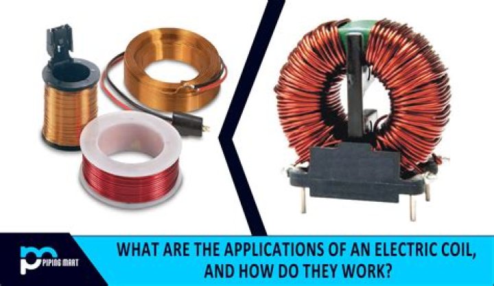
What is a coil made of?
An induction coil consists of a central cylindrical core of soft iron on which are wound two insulated coils: an inner or primary coil, having relatively few turns of copper wire, and a surrounding secondary coil, having a large number of turns of thinner copper wire.
What happens if transformer is connected to DC supply?
If the primary of a transformer is connected to the DC supply, the primary will draw a steady current and hence produce a constant flux. Consequently, no back EMF will be produced.
What frequency does RF transformer use?
RF is considered to be the lowest band of frequencies in this group, and transformers working at frequencies between 30kHz to 30MHz may often have their windings “tuned” to a particular frequency by the addition of a small capacitor to one winding as shown in Fig. 11.5. 1.
How do RF transformers work?
Wideband RF transformers are wound using twisted wires which behave as transmission lines, and the required coupling occurs along the length of these lines as well as magnetically via the core. Transformers having a turns ratio of 1:1, for example, are typically designed for use in a 50- or 75-ohm system.