How to Draw Moment Diagrams
- The area of the first region in the shear diagram is . Draw a straight line from zero to -50ft*lb underneath the support at A.
- The area of region 2 of the shear graph is .
- The area of the triangular region 4 is , bringing the graph to 17.4 lbft.
- Region 5 is also a triangle.
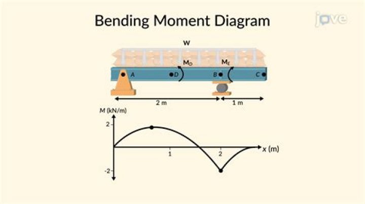
What is a moment on a beam?
Bending Moment is the torque that keeps a beam together (anywhere along the beam). It is found by cutting the beam, then calculating the MOMENT needed to hold the left (or right) half of the beam stationary. If this is done for the other (left) side you should get the same answer – but opposite direction.
How are shear and moment diagrams created?
The general steps for shear and moment diagrams are as follows: Construct a free-body-diagram (FBD) and solve for all unknown reaction forces. Cut the beam (one cut for each beam segment), draw a FBD, and solve for the unknown M and V at the cut in terms of x. Plot the moment and shear equations developed in step 3.
Do bending moment diagrams end at zero?
Bending Moments Diagram: At the ends of a simply supported beam the bending moments are zero. At the wall of a cantilever beam, the bending moment equals the moment reaction. At the free end, the bending moment is zero.
What is moment analysis?
Principal Moment Analysis is a method designed for dimension reduction, analysis and visualization of high dimensional multivariate data. Through this https URL we provide an implementation, together with a graphical user interface, of a simplex based version of Principal Moment Analysis.
What is moment in structural analysis?
In solid mechanics, a bending moment is the reaction induced in a structural element when an external force or moment is applied to the element, causing the element to bend. The most common or simplest structural element subjected to bending moments is the beam.